Damage identification of a beam with a variable cross-sectional area
Dawid Cekus
,Mateusz Miara
,Izabela Zamorska
Journal of Applied Mathematics and Computational Mechanics |
 Download Full Text |
 View in HTML format |
 Export citation |
@article{Cekus_2016,
   doi = {10.17512/jamcm.2016.4.03},
   url = {https://doi.org/10.17512/jamcm.2016.4.03},
   year = 2016,
   publisher = {The Publishing Office of Czestochowa University of Technology},
   volume = {15},
   number = {4},
   pages = {23--32},
   author = {Dawid Cekus and  Mateusz Miara and  Izabela Zamorska},
   title = {Damage identification of a beam with a variable cross-sectional area},
   journal = {Journal of Applied Mathematics and Computational Mechanics}
}
TY - JOUR DO - 10.17512/jamcm.2016.4.03 UR - https://doi.org/10.17512/jamcm.2016.4.03 TI - Damage identification of a beam with a variable cross-sectional area T2 - Journal of Applied Mathematics and Computational Mechanics JA - J Appl Math Comput Mech AU - Cekus, Dawid AU - Miara, Mateusz AU - Zamorska, Izabela PY - 2016 PB - The Publishing Office of Czestochowa University of Technology SP - 23 EP - 32 IS - 4 VL - 15 SN - 2299-9965 SN - 2353-0588 ER -
Cekus, D., Miara, M., & Zamorska, I. (2016). Damage identification of a beam with a variable cross-sectional area. Journal of Applied Mathematics and Computational Mechanics, 15(4), 23-32. doi:10.17512/jamcm.2016.4.03
Cekus, D., Miara, M. & Zamorska, I., 2016. Damage identification of a beam with a variable cross-sectional area. Journal of Applied Mathematics and Computational Mechanics, 15(4), pp.23-32. Available at: https://doi.org/10.17512/jamcm.2016.4.03
[1]D. Cekus, M. Miara and I. Zamorska, "Damage identification of a beam with a variable cross-sectional area," Journal of Applied Mathematics and Computational Mechanics, vol. 15, no. 4, pp. 23-32, 2016.
Cekus, Dawid, Mateusz Miara, and Izabela Zamorska. "Damage identification of a beam with a variable cross-sectional area." Journal of Applied Mathematics and Computational Mechanics 15.4 (2016): 23-32. CrossRef. Web.
1. Cekus D, Miara M, Zamorska I. Damage identification of a beam with a variable cross-sectional area. Journal of Applied Mathematics and Computational Mechanics. The Publishing Office of Czestochowa University of Technology; 2016;15(4):23-32. Available from: https://doi.org/10.17512/jamcm.2016.4.03
Cekus, Dawid, Mateusz Miara, and Izabela Zamorska. "Damage identification of a beam with a variable cross-sectional area." Journal of Applied Mathematics and Computational Mechanics 15, no. 4 (2016): 23-32. doi:10.17512/jamcm.2016.4.03
DAMAGE IDENTIFICATION OF A BEAM WITH A VARIABLE CROSS-SECTIONAL AREA
Dawid Cekus1, Mateusz Miara2, Izabela Zamorska3
1, 2 Institute
of Mechanics and Machine Design Foundations
3 Institute of Mathematics
Czestochowa University of Technology, Częstochowa, Poland
cekus@imipkm.pcz.pl, miara@imipkm.pcz.pl, izabela.zamorska@im.pcz.pl
Received: 21 October
2016; accepted: 23 November 2016
Abstract. In the paper, the process of identification of crack parameters occurring in the cantilever beam with the variable cross-sectional area has been presented. For identification, the non-destructive vibration method has been applied. The analytical solution of the free vibration problem of the beam described according to the Bernoulli-Euler theory has been obtained with the help of Green’s functions.
Keywords: Bernoulli-Euler beam, crack, damage, free vibration, Green’s function, identification, vibration method
1. Introduction
A non-destructive methods are used in order to detect structural damage. These methods allow one to specify the parameters of the defect and the assessment of the strength of the examined element with as small as possible interference in the test object. Non-destructive methods are: a visual method, a penetration method, a magnetic particles method, a radiographic method, an ultrasonic method and a vibration method.
The visual method [1] involves performing inspection of an examined element by skilled personnel. This allows one to obtain the following information about the object: structural quality, roughness, presence or absence and the extent of damage. The penetration technique [2] consists of cleaning the test surface, covering it with a penetrating substance and removing excess material. The next step is the spraying of a substance called a developer, which reacts with the previously imposed substance. This causes gaps to become visible due to penetrated substance changes of color. The magnetic particles method [3] is based on magnetization of the test surface, covering it with fine magnetic particles and puttying a magnet. Verification is done by identifying the agglomeration of particles on the surface of the magnet. The radiographic technique [4] applies the use of X-rays or gamma rays to identify the damage. Principle of operation utilizes a differential based on the absorption between the image of area containing the defect, and the area free of defects. The ultrasonic method [5] consists in the introduction of ultrasonic waves to the test object. These waves move in the element with little damping and velocity dependent on the material properties (mainly elasticity and density). The vibration method [6-14] is based on the measurement of the vibration structure using, for instance, accelerometers or a laser vibrometer. The locations having structural defects lead to changes in the structure characteristics and its dynamics overall.
The papers [6-12] concern the identification of damage occurring in beams/ /columns with a constant cross-sectional area, whereas in the articles [13, 14] the free vibration of the beam with cross-section changed linearly were considered. Authors of [6-14] present the results of experimental studies and/or the results obtained with the use of the finite element method. In this paper, the theoretical vibration method has been applied to identify a crack appearing in the cantilever beam with a nonlinear variable cross-sectional area. The analytical solution of the free vibration problem has been obtained with the help of the Green's function method.
2. Formulation and solution of the free vibration problem of the cantilever beam with variable cross sectional area
The process of identifying damage by use of a frequency is based on the knowledge of a certain number of vibration frequencies of undamaged element and the knowledge of the same number of vibration frequencies of an element with a defect. The number of known frequencies depends on the number of searched parameters of one or more defects. An example of application of the frequency method in the identification process for characteristics of a damage were performed on the cantilever beam with a variable cross-sectional area (Fig. 1). It was assumed that the gap can only occur at one point.
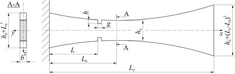
Fig. 1. A scheme of the system under study
The analyzed object is a cantilever beam of length Lb with a damage at the point L of the beam. Variable cross-sectional area A(x) is defined as the product of a constant width b and parabolic varying height of beam h(x).
Figure 2 presents a scheme of the beam’s
approximation by a multistep model [15- 17]. Each of ![]() segments have
constant geometrical parameters and the same physical properties. The damage is
localized at the point x = xn1 = L
and has
the extension g = xn1+1 - xn1.
segments have
constant geometrical parameters and the same physical properties. The damage is
localized at the point x = xn1 = L
and has
the extension g = xn1+1 - xn1.
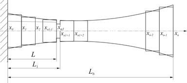
Fig. 2. A sketch of stepped beam
The governing differential motion equation of i-th (i = 1,…,n) segment of the considered system, according to the Bernoulli-Euler theory, is:
| (1) |
where: zi(x,t) is the transverse displacement, EIi is the flexural rigidity, rAi is the mass per unit length of the i-th beam segment and
| (2) |
The functions si(t), mi(t), occurring in (2), are the shear force and bending moment acting on the right end of the i-th segment, δ(·) is Dirac’s delta and δ'(·) is the doublet function (the derivative of the Dirac’s delta [18, 19]). The transverse displacements functions z1, zn satisfy boundary conditions corresponding to the cantilever beam:
| (3) |
and continuity conditions at the dividing points of the segments xi (i = 1,...,n – 1):
| (4) |
Constant parameters EIi, rAi, for i = 1,…, n1, n1 + 2,…, n (for a beam without damage i = 1,…, n) and i = n1 + 1 (damaged segment) are as follows:
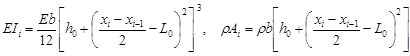 , , | (5) |
| (6) |
After separation of variables: zi(x,t) = Zi(x)coswt, ![]() ,
, ![]() (w - the frequency of free vibrations of a beam) and introducing
parameters:
(w - the frequency of free vibrations of a beam) and introducing
parameters: ![]() ,
, ![]() ,
, ![]() , equation of
motion (1), boundary (2) and continuity (3) conditions may be written as:
, equation of
motion (1), boundary (2) and continuity (3) conditions may be written as:
| (7) |
| (8) |
| (9) |
where ![]() and
and ![]() ,
, ![]() .
.
To solve the problem (7)-(9) the Green’s
function method is used [17, 19]. Green’s function ![]() (
(![]() ) of the linear differential operator
) of the linear differential operator ![]() satisfies the non-homogeneous equation
satisfies the non-homogeneous equation
| (10) |
and may be written in the form
| (11) |
The functions:
| (12) |
constitute a fundamental set of solutions to the homogeneous equation associated with (10).
Assuming that the
functions ![]() are known,
determined solution of (7) has
the form
are known,
determined solution of (7) has
the form
| (13) |
for the coefficients of flexural rigidity
distribution ![]() .
.
Substituting
functions ![]() into continuity conditions (9), we obtain a linear set
of
into continuity conditions (9), we obtain a linear set
of ![]() equations with
equations with ![]() unknown
unknown ![]() :
:
| (14) |
where ![]() ,
, ![]() and
and ![]() (
(![]() ). The nontrivial solution of (14)
exists for the nonsingular main
matrix of the system, its yielding to the equation
). The nontrivial solution of (14)
exists for the nonsingular main
matrix of the system, its yielding to the equation
| (15) |
A non-zero elements ![]() of
matrix
of
matrix ![]() are as follows:
are as follows:
for ![]() :
:
![]()
![]()
![]()
![]()
![]()
![]()
![]()
![]()
for ![]() :
:
![]()
![]()
![]()
![]()
![]()
![]()
![]()
![]()
![]()
![]()
![]()
![]()
for ![]() :
:
![]()
![]()
![]()
![]()
![]()
![]()
![]()
![]()
The frequency equation (15) corresponds to a
stepped cantilever beam if the Green’s functions ![]() (for i =
2,…,n) correspond to the free-free beams and
(for i =
2,…,n) correspond to the free-free beams and ![]() corresponds to the clamped-free beam. The constants
corresponds to the clamped-free beam. The constants ![]() occurring in (11) are
determined on the basis of the appropriate
boundary conditions at the ends of beam segments.
occurring in (11) are
determined on the basis of the appropriate
boundary conditions at the ends of beam segments.
With respect to the frequency ![]() , equation (15) is solved numerically by the use of an approximate method. The mode shapes
corresponding to
, equation (15) is solved numerically by the use of an approximate method. The mode shapes
corresponding to ![]() are in the form
of (13). Assuming
are in the form
of (13). Assuming ![]() ,
other coefficients
,
other coefficients ![]() are determined
from the system (14).
are determined
from the system (14).
3. Sample numerical results of identification of crack parameters
Using the presented model, the algorithm and computer program that enable the determination of the free vibration frequencies of the cantilever beam with variable cross-sectional area has been worked out.
Example results of numerical calculations illustrate the identification of two parameters of damage, i.e. location (L) and height of crack (h). It was assumed that the damage extension is g = 1 mm (Fig. 2). Others parameters of the beam are as follows: Lb = 550 mm, L0 = 225 mm, h0 = 67.272 mm, b = 5 mm. These assumptions cause that only the first three natural frequencies of the undamaged and the damaged beam are required.
On the basis of the determined natural frequencies, the normalization process must be performed. In this case, the normalization is defined as the ratio of the respective frequency of the damaged beam (ωu) to the frequency of the beam without damage (ωn):
| (16) |
Based on the normalization factors, the three-dimensional graphs are created. In Figures 3-5 the change in the values of the first three normalized vibration frequencies depending on the location and height of damage are shown.
On the basis of three-dimensional graphs, the individual contour lines for each examined frequency having the same parameters of the damage must be plotted. As an example, the contour lines for the crack located close to the free end of the beam were plotted (Figures 6-8).
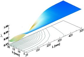
Fig. 3. The first normalized vibration frequency depending on the location (L) and height (h) of the crack
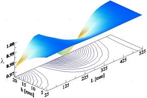
Fig. 4. The second normalized vibration frequency depending on the location (L) and height (h) of the crack
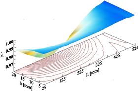
Fig. 5. The third normalized vibration frequency depending on the location (L) and height (h) of the crack
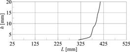
Fig. 6. Contour line for the first normalized vibration frequency
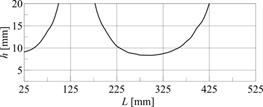
Fig. 7. Contour lines for the second normalized vibration frequency
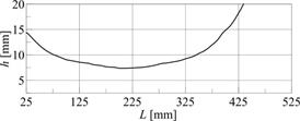
Fig. 8. Contour line for the third normalized vibration frequency
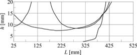
Fig. 9. The identified damage parameters
The intersection of the contour lines presented in Figures 6-8 identifies the location (L) and height (h) of the crack (Fig. 9). As a result of the intersection, the point describing the parameters of the damage (L = 400 mm, h = 14.85 mm) has been obtained. These parameters correspond very well to the assumed values L = 400 mm, h = 15 mm. This means that the method has high accuracy, because the relative error does not exceed 1%.
In the computational models, a rigid restraint is often used. However this type of boundary condition is impossible to achieve in real objects. This results in drawn up theoretical models, in most cases, not being able to express the real structures correctly [20]. Therefore, mathematical models should be experimentally verified. The verification should be applied most of all to undamaged structures. In the case, when the system response diverges from the theoretical results, then an identification of the model must be performed [16].
4. Conclusions
In the present work the identification of the parameters of the crack occurring in the cantilever beam with variable cross-sectional area has been done. For identification, the non-destructive vibration method has been applied. This method requires knowledge of the frequencies of the system without and with the damage. The solution of the free vibration problem of the beam described according to the Bernoulli-Euler theory has been obtained with the help of Green's functions.
Although in this study only exemplary numerical research has been carried out, this method can be successfully used for the identification of damage of real objects. In addition, the method can also be used for verification of defects included in any structure (not only the beams). Identifying structure damage at an early stage has a great influence on the repair cost and has a significant impact on safety.
References
[1] Yamaguchi T., Hashimoto S., Fast crack detection method for large-size concrete surface images using percolation-based image processing, Machine Vision and Applications 2010, August, 21, 5, 797-809.
[2] Miyazaki H., Nomura Y., Sugai H., Iijima M., Inasawa S., Kamiya H., Liquid penetration as a simple detection method for structural differences in particulate films prepared from slurries, Powder Technology 2016, 303, December, 59-67.
[3] Li X., Jiang H., Yin G., Detection of surface crack defects on ferrite magnetic tile, Journal of Sound and Vibration 2016, 375, 4, August, 200-216.
[4] Boaretto N., Centeno T.M., Automated detection of welding defects in pipelines from radiographic images DWDI, NDT & E International, DOI: org/10.1016/j.ndteint.2016.11.003.
[5] Mezil S., Chigarev N., Tournat V., Gusev V., Evaluation of crack parameters by a nonlinear frequency-mixing laser ultrasonics method, Ultrasonics 2016, 69, July, 225-235.
[6] Batabyal A.K., Sankar P., Paul T.K., Crack detection in cantilever beam using vibration response, Vibration Problems ICOVP-2007, 126 of the series Springer, Proceedings in Physics, 27-33.
[7] Bhinge K.V., Karajagi P.G., Kulkarni S.S., Crack detection in cantilever beam by vibration techniques, International Journal of Advanced Engineering Research and Studies 2014, 80-86.
[8] Deokar A.V., Wakchaure V.D., Experimental Investigation of Crack Detection in Cantilever Beam Using Natural Frequency as Basic Criterion, Institute of Technology, Nirma University, Ahmedabad 2011.
[9] Meshram N.A., Pawar V.S., Analysis of crack detection of a cantilever beam using finite element analysis, International Journal of Engineering Research & Technology 2015, 4, 04, April.
[10] Owolabi G.M., Swamidas A.S.J., Seshadri R., Crack detection in beams using changes in frequencies and amplitudes of frequency response functions, Journal of Sound and Vibration 2003, 265, 1-22.
[11] Yamuna P., Sambasivarao K., Vibration analysis of beam with varying crack location, International Journal of Engineering Research and General Science 2014, 2, 6, October-November.
[12] Sokół K., Linear and nonlinear vibrations of a column with an internal crack, J. Eng. Mech. 2014, 140(5), 04014021, DOI: org/10.1061/(ASCE)EM.1943-7889.0000719.
[13] Miara M., Zastosowanie eksperymentalnej analizy modalnej do wykrywania uszkodzeń konstrukcji, Praca inżynierska, Politechnika Częstochowska, WIMiI, 2015.
[14] Zamorska I., Cekus D., Miara M., Effect of crack parameters on free vibrations of the Berrnoulli-Euler beam, Journal of Applied Mathematics and Computational Mechanics 2015, 14(4), 167-174, DOI: 10.17512/jamcm.2015.4.17.
[15] Cekus D., Modelowanie, identyfikacja i badania dynamiki układów mechanicznych, seria Monografie nr 275, Wydawnictwo Politechniki Częstochowskiej, Częstochowa 2013.
[16] Cekus D., Waryś P., Identification of parameters of discrete-continuous models, AIP Conf. Proc. 2015, 1648, 850055, DOI: org/10.1063/1.4913110.
[17] Kukla S., Zamojska I., Frequency analysis of axially loaded stepped beams by Greens’s function method, Journal of Sound and Vibration 2007, 300, 1034-1041.
[18] Mikusiński J., Sikorski R., Elementarna teoria dystrybucji, PWN, Warszawa 1964.
[19] Kukla S., Funkcje Greena i ich zastosowania, Seria Monografie nr 170, Wydawnictwo Politechniki Częstochowskiej, Częstochowa 2009.
[20] Pozorski Z., Pozorska J., Stress redistribution at the support of a transversely loaded sandwich panel, [in:] Advances in Mechanics: Theoretical, Computational and Interdisciplinary Issues, Eds. M. Kleiber, T. Burczyński, K. Wilde, J. Górski, K. Winkelmann, Ł. Smakosz, CRC Press, 2016, 485-488.
