Numerical analysis of stress distribution generated in polyethylene inserts by knee joint endoprotheses' sleds made of different titanium alloys
Marcin Nabrdalik
Journal of Applied Mathematics and Computational Mechanics |
 Download Full Text |
NUMERICAL ANALYSIS OF STRESS DISTRIBUTION GENERATED IN POLYETHYLENE INSERTS BY KNEE JOINT ENDOPROSTHESES’ SLEDS MADE OF DIFFERENT TITANIUM ALLOYS
Marcin Nabrdalik
Institute of Mechanical Technology,
Czestochowa University of Technology
Częstochowa, Poland
marcin@iop.pcz.pl
Abstract. The paper presents analysis of stress distribution in the friction node of knee joint endoprosthesis where sleds are made of various titanium and CoCrMo alloys and cooperate with flat polyethylene inserts. Currently used titanium alloys consist of Nb, Ta, Zr or Mo and with lesser value of Young’s modulus than Ti6Al4V alloy, or steel CoCrMo, which significantly varies from other metal materials. The analysis was conducted with numerical method of ADINA System 8.6. The Finite Elements Method makes it possible to compute and present stress distribution quickly in all elements of the model.
Keywords: endoprosthesis, FEM, contact stress, titanium alloys
1. Introduction
The paper’s objective was to analyze the state of stress occurring on the contact surfaces of metal sleds cooperating with a flat polyethylene insert in knee joint endoprosthesis. It is to select the most suitable material that sleds should be made of in order to achieve an optimum stress distribution on the insert’s surface. The most requested parameters of the materials are:
– biotolerance,
– corrosion resistance,
– wear resistance,
– high tenacity values.
The materials for implants should be of the low Young’s modulus (as close to the bone elasticity as possible), and low weight density. Titanium and its alloys with niobium [1, 2] present those features. When the Young’s modulus value is close to one of the bones being implanted (tibia or femur) it very positively influences the bio-compatibility of the alloplastics. The relation between the bone and implant is proper as far as stiffness is concerned. It excludes negative bone structure remodeling and stress shielding in the implanted area. When the human body is implanted with a material of totally different elasticity than its own natural one, it leads to a significant backstay of the bone-implant structure. If the Young’s modulus of the material is too high, like in the case of CoCrMo alloy, it causes a decrease of the bone load or its total decay and the implant becomes loose, because growths and restructuring of the bone may only be conducted in proper load conditions.
It is critical to look for materials with elasticity features as close to the natural bone tissue as possible. There are currently new titanium alloys being tested with niobium and zirconium with much lower elasticity modulus of 55¸60 GPa. Titanium alloys like Ti6Al4V and new ones like TiNbZr and TiNbZrTa present very good mechanical features, however a lower value of elasticity modulus of the alloys with niobium proves that the future of alloplastics belongs to them [1, 3, 4].
A low value of Young’s modulus in new titanium alloys may cause a decrease in the value of stress generated in polyethylene inserts, and assure a more stable implementation of the endoprosthesis in the bone. Besides, the mentioned alloys do not contain aluminium (Al), which is harmful for the human body.
Under all those restrictions, it is extremely difficult to find the proper material of which to build a knee joint endoprosthesis. Applying FEM in calculations makes it possible to create a map of stress distribution for each alternative.
2. Stress analysis in the pair sled-flat insert for endoprosthesis by W.LINK
The calculations were conducted for partial endoprosthesis with a flat polyethylene insert. They assigned reduced and contact stresses occurring in polyethylene inserts cooperating with metal sleds made of various titanium alloys and CoCrMo. Polyethylene UHMWPE is the weakest point of the endoprosthesis, which is why it is important to present the reduced stress distribution in the inserts.
To analyze the achieved results, the following formulas have been accepted:
Formula (1) presents physical equations connecting stress and strain tensors’ values in 3D, in isotropic, linear - elastic [5].
|
|
Material constans:
E - Young’s modulus (elasticity),
G - Kirchoff’s modulus (non-dilatational strain),
ν - Poisson’s coefficient when solving the equation, we can define components of the stress as a function of the strain.
3. Reduced stress defined for polyethylene inserts of knee joint
The durability of endoprosthesis depends on mechanical and tribological features of its weakest element, which is the polyethylene insert. The reduced stresses depend on all stress tensor’s components, and are presented by formula (2) [5]:
| (2) |
or
where ![]() - main stress,
- main stress,
![]() - Huber-Mises’s
reduced stress.
- Huber-Mises’s
reduced stress.
Huber-Mises’s strength hypothesis presents the formula (3) [5]
|
|
|
or
|
|
4. Knee joint endoprosthesis by W.LINK
Figure 1 presents the product by W.LINK, which is an example of knee joint endoprosthesis. The femoral part copies the shape of condyles of femur bones. The femoral part is precisely fixed with two pins into the bone.
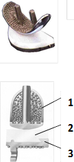
Fig. 1. Knee joint endoprosthesis by W.LINK: 1 - metal sled, 2 - polyethylene insert, 3 - tibia part [5]
The materials used in the above endoprostheses are:
· metal alloy - femoral and tibia part (1 and 2),
· polyethylene UHMWPE - the insert (3).
Metal alloy and polyethylene are the most commonly used pair of materials for knee joint endoprostheses. In some cases the titanium alloy is used as well, due to its high mechanical features and because it is lighter than the CoCrMo alloy.
5. Knee joint endoprosthesis by W.LINK
When designing a simplified numerical model of endoprosthesis, it is important to draw a geometry of the endoprosthesis as true and similar to the real knee joint as possible, not only as far as the shape is concerned but also considering the anatomical range of movements.
5.1. Criteria taken for numerical calculations
The contact stress occurs between two elements pressed together with force. They take place in certain areas and can reach quite high values even at a respectively low value clamp.
Theoretical criteria for contact stress according to Hertz’s theory have been applied in the form as follows:
· Contacting elements are made of homogeneous isotropic materials and according to Hooke’s law.
· The surfaces are fixed in the contact area of the element with smooth and regularly curved surfaces.
· When subjected to load there are only slight strains in the contact area.
· The contact area is relatively small when compared with the surfaces of the contacting elements.
· On the contact area there only normal strains occur.
5.2. Numerical model of knee joint endoprostheses
The numerical model is a simplified version of the original endoprosthesis, though the sleds’ geometry has been maintained. That enables us to keep the general shape of the endoprosthesis and to quite closely imagine the strain distribution on the insert’s surface. The figure below presents the simplified sled model.
The main purpose of the calculations was to define stress distribution on the surface of the polyethylene insert and right underneath it. There were three heights of polyethylene inserts analyzed: 8, 13 and 22 mm, and two sleds of cross-section radiuses of 17 and 27 mm, respectively. The analyzed sleds were made of CoCrMo, Ti6Al4V, Ti13Nb13Zr, Ti12Mo6Zr2Fe, TiNbZrTa. Figure 3 presents the sleds’ geometry of the analyzed knee joint endoprosthesis.
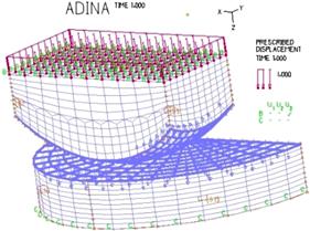
Fig. 2. Simplified sled model used for calculations
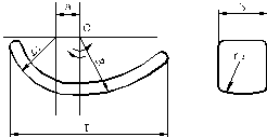
Fig. 3. Knee joint endoprosthesis sled’s geometry. Side and front view
Sleds’ geometric value, accepted as a specific parameter, defined cross-section radius of a sled. Constant geometric diameters are:
· Sled of geometry: R = 28 mm; r1 = 15 mm; r2 = 27 mm; L = 46 mm; b = 17.5 mm,
· Sled of geometry: R = 26 mm; r1 = 16 mm; r2 = 17 mm; L = 45 mm; b = 16 mm.
Polyethylene insert’s dimensions are presented in Figure 4.
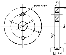
Fig. 4. Geometry and dimensions of a flat polyethylene insert
The most important dimension in the analysis is the height of the insert defined as G. G1 = 8 mm, G2 = 13 mm, G3 = 22 mm.
The 30 numerical analyses were conducted for three various thicknesses of poly- ethylene inserts cooperating with two geometrically different sleds made of five different alloys. Each pair was subjected to load F = 1500 N. Simulations of the cases were conducted with the following, accepted physical features of the materials presented in Table 1.
Table 1
Mechanical features and weight density of the materials used for endoprostheses [6]
|
|
Young’s modulus E [GPa] |
Poisson’s coefficient n |
Weight density r [kg/m3] |
|
CoCrMo |
210 |
0.29 |
8300 |
|
Ti6Al4V |
110 |
0.3 |
4500 |
|
Ti13Nb13Zr |
80 |
0.3 |
4510 |
|
Ti12Mo6Zr2Fe |
73 |
0.3 |
4510 |
|
TiNbZrTa |
53 |
0.3 |
4490 |
|
UHMWPE |
0.01 |
0.4 |
960 |
6. The results of numerical analysis conducted with the use of the Finite Elements Method and ADINA System 8.6.
The calculations prove that stress in endoprosthesis is concentrated in the polyethylene insert, right underneath the contact area of both elements, and highest stress is located right underneath the insert’s surface [7]. Some examples of the calculations are present in Figures 5-7.
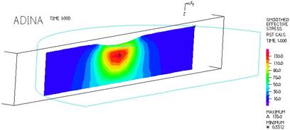
Fig. 5. Contact stress distribution occurring in a flat polyethylene insert. Flat insert 8 mm thick cooperates with a sled of radius 17 mm. Load 1500 N [7]
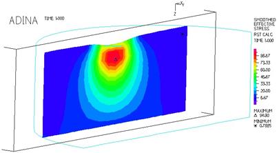
Fig. 6. Contact stress distribution occurring in a flat polyethylene insert. Flat insert 13 mm thick, cooperates with sled of radius 27 mm. Load 1500 N [7]
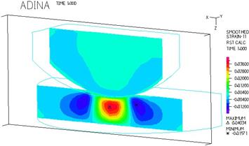
Fig. 7. Strain distribution occurring in a flat polyethylene insert. Flat insert 8 mm thick, cooperates with sled of radius 27 mm. Load 1500 N [7]
7. Remarks on the results of the calculations
The lowest reduced stress was achieved for the model where the sled’s cross-section radius is 27 mm, and the sled is made of TiNbZrTa alloy and valued 9.29 MPa. The highest stress occurred in the model where the sled was made of CoCrMo alloy, and valued 38.85 MPa, and the sled’s cross-section radius was the smallest and valued 17 mm. Figure 8 presents the influence of the cross-section radius of the sled, thickness of the insert and kind of material which the sled is made of, on the value of the stress generated in the flat polyethylene insert.
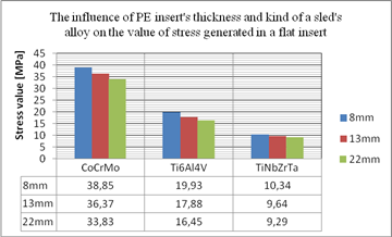
Fig. 8. Influence of the sled’s cross-section radius and insert’s thickness on the value of the stress generated in the flat UHMWPE insert
7.1. Conclusions
1. The conducted numerical calculations and analysis undoubtedly prove that the future of knee joint alloplastics belongs to a group of new materials including titanium alloys, which when appropriately selected and combined as far as mechanical features are concerned (low Young’s modulus value), may significantly decrease the value of stress generated in polyethylene elements of endoprostheses.
2. Another important element influencing the durability of endoprostheses is the optimizing of the geometry of the implants both in the friction node and fixing area in the bone.
References
[1] Gierzyńska-Dolna M., Tribological problems in natural and artificial human joint, Inżynieria Biomateriałów 1997, 19-28.
[2] Long M., Rack H.J., Titanium alloys in total joint replacement - a materials science perspective, Biomaterials 1998, 19, 1621-1639.
[3] Gierzyńska-Dolna M., Biotribologia, Wydawnictwo Politechniki Częstochowskiej, Częstochowa 2002.
[4] Gierzyńska-Dolna M., Kubacki J., Specyfika zużycia endoprotez stawu biodrowego i kolano- wego, Mat. II Sympozjum Inż. Ortop. i Prot. IOP’99, Białystok 1999, 45-51.
[5] Prospekt firmy W.LINK.
[6] Marciniak J., Biomateriały, Wydawnictwo Politechniki Śląskiej, Gliwice 2002.
[7] Nabrdalik M., Use of the finite element metod in the analysis of load of polyethylene inserts of knee joint endoprostheses, Prace Naukowe Instytutu Matematyki i Informatyki 2012, 1(11), 87-93.
[8] Zienkiewicz O.C., Metoda elementów skończonych, Wyd. Arkady, Warszawa 1972.