Determination of stresses in the steel pipe during the superficial heat treatment process with helical path
Adam Kulawik
,Norbert Sczygiol
,Joanna Wróbel
Journal of Applied Mathematics and Computational Mechanics |
 Download Full Text |
DETERMINATION OF STRESSES IN THE STEEL PIPE DURING THE SUPERFICIAL HEAT TREATMENT PROCESS WITH HELICAL PATH
Adam Kulawik, Norbert Sczygiol, Joanna Wróbel
Institute of Computer and Information
Science, Czestochowa University of Technology
Częstochowa, Poland
adam.kulawik@icis.pcz.pl, norbert.sczygiol@icis.pcz.pl,
joanna.wrobel@icis.pcz.pl
Abstract. In the paper a numerical model for the quench hardening process with the moving heat source of steel pipe made of medium carbon steel have been presented. The constant speed rotation and moving of the pipe was assumed to obtain the path of the heat source in the shape of the helical line. In this model the relationship occurring between thermal phenomena, phase transformation in the solid state and mechanical phenomena have been taken into account. The temperature and stress fields are determined using the copyright software based on the finite element method (three-dimensional tasks). To calculate the phase content in the solid state, the macroscopic model based on the analysis of the CTP diagrams is used. The range of the martensite transformations depends on the value of stresses. In the model the tempering phenomena is also taken into account. In the model of mechanical phenomena the elastic, thermal, structural, plastic strains and transformations plasticity are considered.
Keywords: numerical analysis, superficial heat treatment, phase transformations in the solid state, stresses, steel pipe
1. Introduction
The optimization of production costs of the machine parts at the design stage requires proper selection of material properties, not always the same in the entire area of the workpiece. In the production of machine parts the more cheaper materials are used. In the load area the material properties are improved by using the treatment processes. Therefore, the simulation tools for optimization of industrial processes are used.
One of the basic process, which aims to improve the mechanical properties of the steel part, is quench hardening. In some processes, in which previously the volumetric hardening has been used, often the heat treatment with the moving heat source is applied. The use of this technology allows for more precise control of material parameters and reduces the energy intensity of the process.
2. Numerical model
For modelling of the quench hardening process the complex numerical model taking into account thermal phenomena, phase transformations in the solid state and mechanical phenomena are used. Coupling between elements of the model (see Fig. 1) such as: latent heat of phase transformations (unimportant phenomena during the superficial hardening process), structural and thermal strains as well as transformation plasticity should also be taken into consideration. The influence of temperature and phase composition on the properties of hardened material (heat transfer coefficient, thermal capacity, Young's modulus and yield point for the appropriate phase) and influence of the stress state on the range of phase transformations should also be presented on this model.
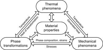
Fig. 1. The diagram of numerical model for quench hardening process
To determine the temperature fields, in the next time steps, the solution of the heat transfer equation based on the finite element method is used
| (1) |
where: T is temperature [K], t is time [s], λ = λ(T) is the thermal conductivity [W/(m∙K)], ρ is the density [kg/m3], C is the effective thermal capacity [J/(kg∙K)].
The superficial heat source (Neumann boundary condition) in the simulation of the heating process is determined by the function
| (2) |
![]() where: Q is the power of the source [W], R is the
radius of the source,
where: Q is the power of the source [W], R is the
radius of the source, ![]()
![]()
![]() the angle of the position of the
source, rz is
the external radius.
the angle of the position of the
source, rz is
the external radius.
To calculate the kinetic of phase transformations in the solid state during the heating and cooling processes, the macroscopic model based on the analysis of CTP diagrams is used.
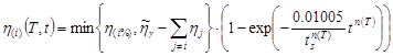
The fraction of the austenite phase during heating is determined on the basis of modified Koistinen-Marburger equation [1]
| (3) |
The phase transformations during the cooling process are calculated by the Johnson-Mehl-Avrami-Kolmogorov equation
 | (4) |
where: η(i%) is the final fraction of “i” phase estimation on the basis of CCT diagrams for considered steel, n(T) the functions depending on the start and finish times of transformation (ts and tf), Tsg and Tfg are the temperature of start and finish of austenite transformation.
Increment of martensite phase is described by the Koistinen-Marburger equation [1, 2]
| (5) |
where: seff is effective stress, MS is the start temperature of martensite transformation, AM and BM are material coefficients.
The martensite tempered fraction resulting from tempering is described by formula
| (6) |
The curves of start and finish of the tempering transformations were determined on the basis of equations dependent on the heating speed [3].
The thermal and structural strains are calculated by the following equations
| (7) |
where: ![]() is a
thermal expansion coefficients for “i” phase,
is a
thermal expansion coefficients for “i” phase, ![]() is a strain expansion coefficient
for “i” transformation.
is a strain expansion coefficient
for “i” transformation.
In the model of mechanical phenomena the equilibrium equation was used without mass forces. The equilibrium equations are supplemented by the constitutive relations in the form
| (8) |
where: ee, e, epl, etp are respectively the elastic, total, plastic and transformation strain tensors, D is tensor of material constants.
The plastic strains (epl) are determined by using the associated plastic flow law with isotropic hardening [4]. To calculate transformations plasticity (etp) the model based on the Greenwood-Johnson mechanism is used [4, 5]. The temporary yield point is dependent on the temperature and the phase composition.
3. Numerical simulation
The numerical simulation of the quench hardening process was performed for the pipe made of C45 steel. It was assumed that the considered object is only a part of a larger steel element which was assumed by appropriate conditions on the edge GB . The dimensions of the medium carbon steel pipe are following: the length of the element 0.05 m, internal radius rw = 0.0225 m and external radius rz = 0.025 m (Fig. 2).
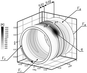
Fig. 2. Graphical interpretation of the described example
The following conditions to modelling of the quench hardening process were assumed:
· the initial temperature (T0) in the whole area is equal to 293 K,
· the thermophysical properties such as: heat transfer coefficient, thermal capacity, Young’s modulus and yield point for the appropriate phase depends on the temperature and phase composition [6],
· the parameters of the heat source: position z = 0.02 m, superficial heat source R = 0.0033 m, Q = 1800 W, hardening speed Vφ = 0.02 m/s (0.8 rad/s),
· on boundaries GF, GO, GI the Newton boundary condition (cooling in the air) with Tair = 293 K, (αair) [7],
· on boundary GB the Dirichlet boundary conditions Ux = Uy = Uz = 0, T = 293 K.
|
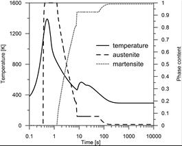
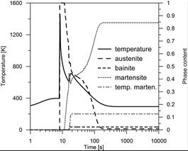
Fig. 3. Changes of temperature and phase fractions (austenite, bainite, martensite, tempered martensite) in control nodes: a) first control node, b) second control node
Results of numerical calculations showing the kinetic of phase transformations, distribution of temperature in two control nodes: p1(0.0077, 0.0238, 0.0204) and p2(0.0077, 0.0238, 0.0316) are depicted in Figures 2 and 3.
The path of the heat source in the shape of the helical line caused the influence of temperature on the next waveforms to be greater with the increasing of the temperature of element. Due to the gradual heating of the element the width of the heat affected zone is increasing. On the next paths the particular importance has the tem- pering process. Because of the shape of the path, the tempering process takes place only in the areas between the paths.
|
|
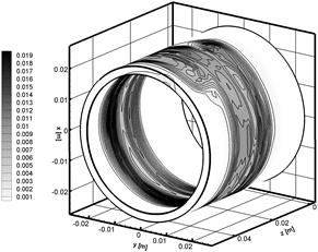
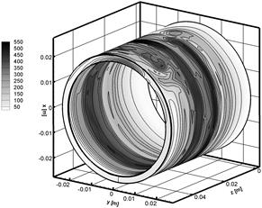
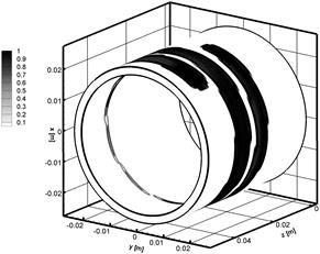
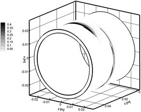
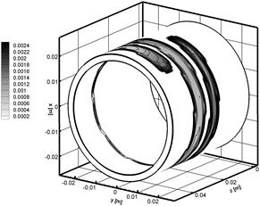
Fig. 4. Distributions of: a) martensite fraction, b) tempered martensite fraction, c) structural strains, d) residual effective plastic strain, e) residual effective stresses [MPa]
4. Conclusions
The characteristics of the results occurring in such simple technological process indicates on the very complex stress state. The use of heat source with constant power caused the increase of the martensite phase range in the following waveforms. The changes of heat source power should be used to obtain uniform zones of martensite. Due to the use of a helical line of the heat source, the stress state is much more uniform than in the case of using circular paths (see Fig. 4) [8]. All calculations were performed on the copyrighted software implemented in C++ language.
References
[1] Koistinen D.P., Marburger R.E., A general equation prescribing the extent of the austenite-martensite transformation in pure iron-carbon alloys and plain carbon steels, Acta Metallica 1959, 7, 59-60.
[2] Geijselaers H.J.M., Numerical simulation of stresses due to solid state transformations. The simulation of laser hardening, Thesis, University of Twente, The Netherlands 2003.
[3] Winczek J., Kulawik A., Dilatometric and hardness analysis of C45 steel tempering with different heating-up rates, Metalurgija 2012, 51 (1), 9-12.
[4] Bokota A., Modelowanie hartowania stali narzędziowych. Zjawiska cieplne, przemiany fazowe, zjawiska mechaniczne, Monografie nr 233, Wydawnictwo PCz, Częstochowa 2012.
[5] Fischer F.D., Reinsner G., Werner E., Tanaka K., Cailletaud G., Antretter T., A new view on transformation induced plasticity (TRIP), International Journal of Plasticity 2000, 16, 723-748.
[6] Coret M., Combescure A., A mesomodel for numerical simulation of the multiphasic behavior of materials under anisothermal loading (application to two low-carbon steels), International Journal of Mechanical Sciences 2002, 44, 1947-1963.
[7] Li C., Wang Y., Zhan H., Han T., Han B., Zhao W., Three-dimensional finite element analysis of temperatures and stresses in wide-band laser surface melting processing, Materials and Design 2010, 31, 3366-3373.
[8] Kulawik A., Wróbel J., The determination of the strains for the multipath heat source of the hardening process, Modelowanie Inżynierskie 2013, 47(16), 123-128 (in Polish).
[9] Mochnacki B., Nowak A., Pocica A., Numerical model of superficial layer heat treatment using the TIG method, Polska metalurgia w latach 1998-2002, t. 2, Komitet Metalurgii PAN, WN AKAPIT, Kraków 2002, 229-235.