Mathematical modeling of mechanical phenomena in the gantry crane beam
Leszek Sowa
,Paweł Kwiatoń
Journal of Applied Mathematics and Computational Mechanics |
 Download Full Text |
 View in HTML format |
 Export citation |
@article{Sowa_2017,
   doi = {10.17512/jamcm.2017.3.09},
   url = {https://doi.org/10.17512/jamcm.2017.3.09},
   year = 2017,
   publisher = {The Publishing Office of Czestochowa University of Technology},
   volume = {16},
   number = {3},
   pages = {97--104},
   author = {Leszek Sowa and  Paweł Kwiatoń},
   title = {Mathematical modeling of mechanical phenomena in the gantry crane beam},
   journal = {Journal of Applied Mathematics and Computational Mechanics}
}
TY - JOUR DO - 10.17512/jamcm.2017.3.09 UR - https://doi.org/10.17512/jamcm.2017.3.09 TI - Mathematical modeling of mechanical phenomena in the gantry crane beam T2 - Journal of Applied Mathematics and Computational Mechanics JA - J Appl Math Comput Mech AU - Sowa, Leszek AU - Kwiatoń, Paweł PY - 2017 PB - The Publishing Office of Czestochowa University of Technology SP - 97 EP - 104 IS - 3 VL - 16 SN - 2299-9965 SN - 2353-0588 ER -
Sowa, L., & Kwiatoń, P. (2017). Mathematical modeling of mechanical phenomena in the gantry crane beam. Journal of Applied Mathematics and Computational Mechanics, 16(3), 97-104. doi:10.17512/jamcm.2017.3.09
Sowa, L. & Kwiatoń, P., 2017. Mathematical modeling of mechanical phenomena in the gantry crane beam. Journal of Applied Mathematics and Computational Mechanics, 16(3), pp.97-104. Available at: https://doi.org/10.17512/jamcm.2017.3.09
[1]L. Sowa and P. Kwiatoń, "Mathematical modeling of mechanical phenomena in the gantry crane beam," Journal of Applied Mathematics and Computational Mechanics, vol. 16, no. 3, pp. 97-104, 2017.
Sowa, Leszek, and Paweł Kwiatoń. "Mathematical modeling of mechanical phenomena in the gantry crane beam." Journal of Applied Mathematics and Computational Mechanics 16.3 (2017): 97-104. CrossRef. Web.
1. Sowa L, Kwiatoń P. Mathematical modeling of mechanical phenomena in the gantry crane beam. Journal of Applied Mathematics and Computational Mechanics. The Publishing Office of Czestochowa University of Technology; 2017;16(3):97-104. Available from: https://doi.org/10.17512/jamcm.2017.3.09
Sowa, Leszek, and Paweł Kwiatoń. "Mathematical modeling of mechanical phenomena in the gantry crane beam." Journal of Applied Mathematics and Computational Mechanics 16, no. 3 (2017): 97-104. doi:10.17512/jamcm.2017.3.09
MATHEMATICAL MODELING OF MECHANICAL PHENOMENA IN THE GANTRY CRANE BEAM
Leszek Sowa, Paweł Kwiatoń
Institute of Mechanics and Machine Design
Fundamentals, Czestochowa
University of Technology
Czestochowa, Poland
sowa@imipkm.pcz.pl, kwiaton@imipkm.pcz.pl
Received: 20 May 2017; Accepted: 9 September 2017
Abstract. This work concerns the numerical analysis of the gantry crane beam in the context of the safety of the structure. The mathematical model and numerical simulations of mechanical phenomena in the gantry crane beam are presented in this paper. The analysed gantry crane beam has a T-section. As a result of the computations carried out, the stresses and displacements of the gantry structure were obtained. The influence of the value and loading force position on the equivalent stress in the gantry crane beam was evaluated. It was sought that the maximum value of Huber-Mises-Hencky stress induced in the beam was less than the strength of material, so the design is safe.
MSC 2010: 74A10, 74S05, 65C20, 68U20
Keywords: mathematical modelling, stress analysis, numerical simulation, FEM
1. Introduction
The gantry cranes are currently one of the most common devices for transporting heavy loads from one position to another and can be applied in many industry areas. They are mainly used in car factories, heavy industry and shipyards. The range of cranes includes: single girder, double girder, double leg and single leg. Cranes can also have different load capacity, span and height. The construction of an overhead crane with a double girder is often analyzed [1-4], while a single beam is usually used in the gantry crane [5]. This type of structure is analyzed in this paper. Many current papers are aimed at the improvement of the strength of the crane girder structure. These efforts help to overcome damage of the crane girders [1-7]. The design of modern mechanical constructions is a complex task that requires the use of suitable tools. Experimental research is costly and time consuming [7]. Therefore, an appropriate tool appears to be numerical simulation which uses the finite element method (FEM), for example [2-6]. Crane structures are subjected to moving loads. The problem of moving load is a very important topic in the design of large gantry cranes. Dynamic effects caused by moving loads are not often considered [8]. Usually, the load movement is neglected and a numerical analysis is performed for a certain position of load [2-4, 6]. The analysis of mechanical phenomena in several selected positions of load can be found in [5].
The purpose of this paper is to estimate the value of the stresses generated in the gantry crane beam depending on the values of the loads assumed and the beam shape, so that the beam is not damaged. The issues of stress concentration and localization of extreme deformations will also be discussed. For this purpose, numerical simulations were performed to obtain the distribution of stresses, displacements and strains. The value of the calculated maximum stresses is compared to the permissible stresses of the beam material. When the condition of strength is met, then the structure is considered to be safe.
2. Mathematical and numerical models
The analysis of mechanical phenomena in the elastic range was made using the equilibrium equations (1), supplemented by constitutive relations (2a), strain-displacement relationships (2b) and boundary conditions (3). The mathematical model is based on the solution of the following system of equations [5, 9, 10]:
| (1) |
| (2) |
| (3) |
where σij is stress tensor, εks - strains tensor, ui - displacement vector, Dijks denotes the matrix of elasticity (a tensor of material properties) and pi is components of force per unit area acting on a plane (Γ) with normal nj.
The numerical model uses the finite element method and is derived from the criterion of the method of weighted residuals [2-10]. Equation (1) is multiplied by the weighting function and integrated over the considered region. As the result of using Gauss-Green's theorem and the Galerkin method, which were described in the work [9, 10], the following matrix equation is obtained [5, 9, 10]:
| (4) |
where K is the stiffness matrix, u - sought displacement vector, R - vector associated with the loads and boundary conditions.
The solution of (4) is obtained in the form of nodal displacement in the considered region. Next, using the equation (2), the sought fields of stresses are obtained.
3. Description of the problem
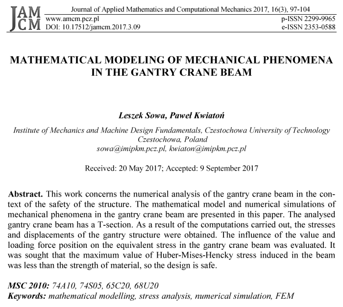
To analyze the influence of position and the value of load on the stress distribution in the gantry crane, the static system of a single-span beam was considered (Fig. 1).
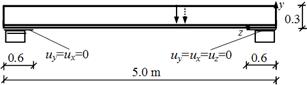
Fig. 1. The static system of analyzed gantry crane structure
The gantry crane beam with a length of 5 m is located on two supporting columns with a width of 0.6 m. One end of the beam (left) is free to shift along the z-axis and the second end cannot move in three directions. Appropriate displacements are set to zero at the beam ends’ contact surfaces to the support columns. The cross section of the beam is a T-section with dimensions 295x125x10x15 mm. The results of numerical simulations obtained for this beam are compared with the results of analyses performed for the beam with I-section of dimensions 320x125x10x15 mm (depth x flange width x web thickness x flange thickness) [5].
The structure is loaded by pressure perpendicular to the bottom flange of the beam and directed downwards, i.e. opposite to the y-axis. The pressure value is due to the total weight of the loaded crane trolley that can move along the bottom flange of the crane beam. The movement of the crane trolley is carried out by shifting the pressure, which acts on the contact surface of the trolley wheels with the beam, to successive positions along the crane beam, ignoring inertia effects. The assumed pressure value of 14.42 MPa multiplied by the contact surface of the trolley wheels with the beam corresponds to the force equal to 45 kN. The pressure of 16.03 MPa corresponds to the force of 50 kN. In numerical calculations, the following elasticity constants for S235 steel were used: Young's modulus (E) equal to 2.05e+5 MPa, the Poisson’s ratio (ν) of 0.29 and the yield strength (Re) of 235 MPa [2-6]. The value of the allowable stress of the steel beam material (σall) amounts to 120 MPa. The value of these stresses results from the division of the yield strength by the safety factor which is assumed to be equal to 1.96. The safety factor should be assumed between 1.5 and 3 for crane girder design as recommended [2, 3].
The analysis of the stresses of the gantry crane structure was made using professional software (GeoStar) supplemented by an additional force movement procedure. The gantry crane beam has been discretized by a mesh of 8989 nodes, which define 6000 finite elements. In this study, a 3D 8-node isoparametric element type solid is used. The research performed in order to increase the strength of the structure of the gantry crane allow for the evaluation of the stress state, pointing out the critical areas and values.
4. Example of numerical calculations
In this study, the numerical analysis of the stresses, strains and displacements of the gantry crane structure is made. The influence of changing the loading force position on the equivalent stress (σeq) in the beam was evaluated. The Huber-Mises- -Hencky stress distributions in the beam (T-section) for various positions of the load F = 45 kN are shown in Figures 2-4. The strength condition was checked using the value of generated stresses in successive loading force positions. We tried to that the maximum value of the Huber-Mises-Hencky stress induced in the gantry crane beam was less than the strength of beam material (σeq < σall), because only then the design is safe. Generally, the area of increased stresses is related to the current position of load and moves with it, achieving a maximum value in the middle of the beam span. The displacement and strain field of the gantry crane structure is shown in Figures 5 and 6, when these magnitudes reached a maximum value for the central position of load. In order to verify the value of the obtained displacement, the ratio of vertical displacement in the half of the beam to the beam length should be checked [6]. If the beam with a T-section was loaded with a force of 50 kN (Fig. 7), the strength condition was not met, therefore another cross section of the beam should be applied, for example the I-section. The equivalent stress distribution in the gantry crane beam (I-section) for middle positions of the load are shown in Figure 8. The research performed allows for the evaluation of the stress state, pointing out the critical areas and values. They were made in order to increase the structure strength of the gantry crane.
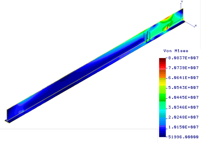
Fig. 2. Huber-Mises-Hencky stress distribution [Pa] in the beam for location z = 1 m of the load F = 45 kN

Fig. 3. Huber-Mises-Hencky stress distribution [Pa] in the for location z = 2.5 m of the load F = 45 kN
Fig. 4. Huber-Mises-Hencky stress distribution [Pa] in the beam for location z = 3.5 m of the load F = 45 kN
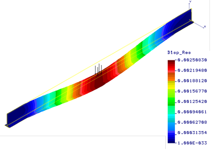
Fig. 5. Displacement field [m] in the beam for location z = 2.5 m of the load F = 45 kN
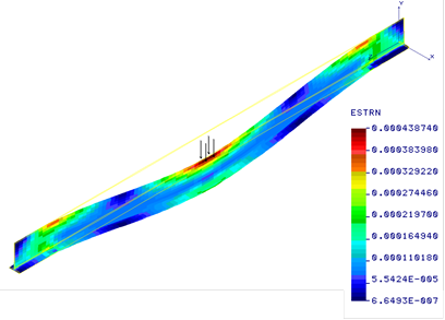
Fig. 6. Strain field in the beam for location z = 2.5 m of the load F = 45 kN
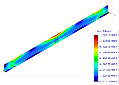
Fig. 7. Huber-Mises-Hencky stress distribution [Pa] in the beam (T-section) for location z = 2.5 m of the load F = 50 kN
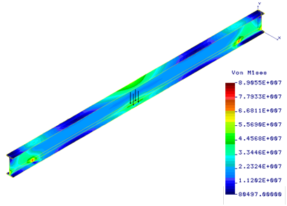
Fig. 8. Huber-Mises-Hencky stress distribution [Pa] in the beam (I-section) for location z = 2.5 m of the load F = 50 kN
5. Conclusions
In this paper the mathematical model and numerical simulations of mechanical phenomena in the gantry crane beam are presented. The influence of force value and changing the loading force position on the equivalent stress in the beam was evaluated. The region of increased stresses is associated to the current position of load and moves with it (Figs. 2-4). These stresses reach a maximum value in the half of the beam length. The maximum equivalent stresses were less than the strength of the beam material and equalled 116.6 MPa (Fig. 3) in the gantry crane beam with a T-section or 89.1 MPa (Fig. 8) in the beam with an I-section. The strength condition was not met when the beam with a T-section was loaded with a load F = 50 kN (Fig. 7). The ratio of static deflection to beam length is 5.2e-4 and is within acceptable limits [6]. In addition, a peak of stresses is located at the connection between the end of the beam and vertical support column (Figs. 2, 4). Thus, the end of beam needs special attention in case we want to redesign the crane beam structure in order to improve the product and to eliminate any possible tension peak. It should be noted that results of numerical simulations are consistent with the results found in the literature of the subject [2-6]. Similarly, reducing stresses near the end of the beam by improving the construction of gantry crane was recommended.
References
[1] Patel P.R., Patel V.K., A review on structural analysis of overhead crane girder using FEA technique, Int. J. Eng. Sci. Innov. Tech. 2013, 2(4), 41-44.
[2] Suratkar A., Shukla V., Zakiuddin D.K.S., Design optimization of overhead EOT crane box girder using finite element analysis, Int. J. Eng. Res. Tech. 2013, 2(7), 720-724
[3] Alkin B.C., Imrak C.E., Kocabas H., Solid modeling and finite element analysis of an overhead crane bridge, Acta Polyt. 2005, 45(3), 61-67.
[4] Pinca C.B., Tirian G.O., Josan A., Chete G., Quantitative and qualitative study on the state of stresses and strains of the strength structure of a crane bridge, WSEAS Tran. Appl. Theor. Mech. 2010, 5(4), 231-241.
[5] Sowa L., Kwiatoń P., Numerical analysis of stress fields generated in the gantry crane beam, Procedia Eng. 2017, 177, 218-224.
[6] Haniszewski T., Strength analysis of overhead traveling crane with use of finite element method, Tran. Prob. 2014, 9(1), 19-26.
[7] Yang B., Kang S., Xiong G., Nie S., Hu Y., Wang S., Bai J., Dai G., Experimental and numerical study on lateral-torsional buckling of singly symmetric Q460GJ steel I-shaped beams, Thin-Walled Struct. 2017, 113, 205-216.
[8] Gašić V., Zrnić N., Milovančević M., Considerations of various moving load models in structural dynamics of large gantry cranes, FME Transactions 2013, 41, 311-316.
[9] Węgrzyn-Skrzypczak E., Skrzypczak T., Mathematical description of discontinuous Galerkin method in theory of thermoelasticity, Sci. Rese. Inst. Math. and Com. Sci. 2010, 9(2), 235-242.
[10] Bokota A., Domański T., Sowa L., Model and numerical analysis of mechanical phenomena of tools steel hardening, Arch. Foun. Eng. 2010, 10(1), 19-22.