The influence of the heat source model selection on mapping of heat affected zones during surfacing by welding
Jerzy Winczek
Journal of Applied Mathematics and Computational Mechanics |
 Download Full Text |
 View in HTML format |
 Export citation |
@article{Winczek_2016,
   doi = {10.17512/jamcm.2016.3.16},
   url = {https://doi.org/10.17512/jamcm.2016.3.16},
   year = 2016,
   publisher = {The Publishing Office of Czestochowa University of Technology},
   volume = {15},
   number = {3},
   pages = {167--178},
   author = {Jerzy Winczek},
   title = {The influence of the heat source model selection on mapping of heat affected zones during surfacing by welding},
   journal = {Journal of Applied Mathematics and Computational Mechanics}
}
TY - JOUR DO - 10.17512/jamcm.2016.3.16 UR - https://doi.org/10.17512/jamcm.2016.3.16 TI - The influence of the heat source model selection on mapping of heat affected zones during surfacing by welding T2 - Journal of Applied Mathematics and Computational Mechanics JA - J Appl Math Comput Mech AU - Winczek, Jerzy PY - 2016 PB - The Publishing Office of Czestochowa University of Technology SP - 167 EP - 178 IS - 3 VL - 15 SN - 2299-9965 SN - 2353-0588 ER -
Winczek, J. (2016). The influence of the heat source model selection on mapping of heat affected zones during surfacing by welding. Journal of Applied Mathematics and Computational Mechanics, 15(3), 167-178. doi:10.17512/jamcm.2016.3.16
Winczek, J., 2016. The influence of the heat source model selection on mapping of heat affected zones during surfacing by welding. Journal of Applied Mathematics and Computational Mechanics, 15(3), pp.167-178. Available at: https://doi.org/10.17512/jamcm.2016.3.16
[1]J. Winczek, "The influence of the heat source model selection on mapping of heat affected zones during surfacing by welding," Journal of Applied Mathematics and Computational Mechanics, vol. 15, no. 3, pp. 167-178, 2016.
Winczek, Jerzy. "The influence of the heat source model selection on mapping of heat affected zones during surfacing by welding." Journal of Applied Mathematics and Computational Mechanics 15.3 (2016): 167-178. CrossRef. Web.
1. Winczek J. The influence of the heat source model selection on mapping of heat affected zones during surfacing by welding. Journal of Applied Mathematics and Computational Mechanics. The Publishing Office of Czestochowa University of Technology; 2016;15(3):167-178. Available from: https://doi.org/10.17512/jamcm.2016.3.16
Winczek, Jerzy. "The influence of the heat source model selection on mapping of heat affected zones during surfacing by welding." Journal of Applied Mathematics and Computational Mechanics 15, no. 3 (2016): 167-178. doi:10.17512/jamcm.2016.3.16
THE INFLUENCE OF THE HEAT SOURCE MODEL SELECTION ON MAPPING OF HEAT AFFECTED ZONES DURING SURFACING BY WELDING
Jerzy Winczek
Institute of Mechanical Technologies,
Czestochowa University of Technology
Częstochowa, Poland
winczek@imipkm.pcz.pl
Abstract. The paper compares forms and dimensions of heat affected zones determined on the basis of analytical descriptions of temperature fields caused by different models of heat source. In the first case, a single-distributed volumetric heat source model reflecting only the impact of an electric arc was assumed. In further considerations, bimodal heat source models were applied. The first one consists of a volumetric heat source model of weld reinforcement (of melted electrode material) and a surface model of an electric arc. In the second one a bimodal source is the sum of volumetric heat source models of weld reinforcement and an electric arc. Calculations are based on the example of submerged arc welding of a rectangular S355 steel element. The results of numerical simulations were verified experimentally, confirming the argument that it is necessary to include the bimodal heat source in temperature field modelling, which takes into account the temperature rises caused by the heat of melted electrode material.
Keywords: modelling, welding heat source, heat affected zone, submerged arc welding
1. Introduction
First attempts to describe the temperature field in the welding process and related processes were undertaken in the middle of the last century. Rosenthal’s [1] and Rykalin’s [2] works initiated modeling of the temperature field caused by a moving source. In analytical descriptions of the temperature field, the thermo-mechanical properties of the heated material are assumed to be temperature-independent. Rosenthal obtained the equation of the temperature distribution for a quasi-steady state for different heat source models (point, linear and surface). Rosenthal adopted a heat source in the form of a segment parallel to the axis of the weld, whereas Rykalin adopted a heat source in the form of a perpendicular segment.
For analytical description of the temperature field, the solution of the differential heat conduction equation is commonly used [3]:
| (1) |
where r is the radius vector of the considered area point with respect to the heat source, T - temperature, t - time, a - the coefficient of temperature, c - specific heat, ρ - density, Q - heat source.
In the case of a point source for infinite body, the equation solution (1) becomes:
| (2) |
where R is the distance of the considered point from the source, and for a semi-infinite body:
| (3) |
or
| (4) |
Equation (4) determines the temperature value at the point with coordinates x, y, z with the source position at x’,y’.
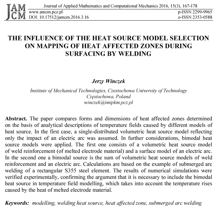
Figure 1 [4] shows a temperature distribution in the semi-infinite body caused by the instantaneous point heat source (4). Thermal properties of the material were assumed in the calculations [4] a = 8·10–6 m2/s, cr = 5,2·106 J/m°C, Q = 3,3·103 J and T0 = 0. Figure 1a shows the heat cycles at points at various distances R from the heat source. In points located close to the weld axis, the temperature values differ significantly from the actual values. Figure 1b presents the temperature distribution on the surface of the heated object in the time range 0.5¸5 seconds from the moment of the applied source.
For time 0.5 s, temperature curves tend asymptotically in relation to the temperature axis, and finally exceeding the evaporation temperature of steel approx. 3000°C.
When we consider a moving point heat source, which is moving on the surface of the semi-infinite body along the x axis of the Cartesian system from x0 point at speed v, then the temperature field at time t from the beginning of action of the heat source at the point with coordinates x, y, z (Fig. 2) will be expressed by the sum of the temperature rises caused by the heat release at elementary time increments dt’:
| (5) |
where x0 is the coordinate
of beginning of the source path and ![]() its power.
its power.
a) b)
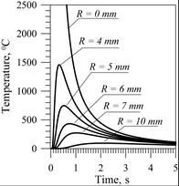
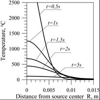
Fig. 1. Temperature near the temporary heat source: a) heat cycles for points at different distances from the source, b) temperature distribution in the body for selected times
Fig. 2. Scheme for determining of the temporary temperature during heating by a moving heat source
Since then, the constant search for models of heat sources and descriptions of the temperature field continues, which would map the temperature distributions as close as possible to the actual.
In the next part of the paper, we discuss different models of a heat source and the result of using some of them to describe the temperature field and to determine the heat-affected zone. A detailed analysis was carried out on the example of submerged arc welding of a rectangular element made of steel S355.
2. Surface and volumetric heat source models
Eagar and Tsai [5] modified Rosenthal’s model by introducing a surface heat source (6) with a Gaussian distribution (Fig. 3) to the description of the temperature field in the semi-infinite body. The Gaussian distribution is characterized by an averaged radius r0 in which the heat volume qmax/e.
| (6) |
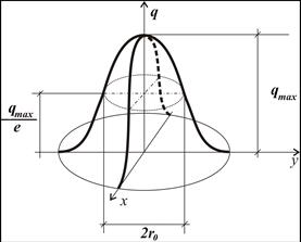
Fig. 3. Surface two-dimensional Gaussian distributed heat source
A double-ellipsoidal, three-dimensional heat source (Fig. 4) was first introduced by Goldak [6]. Two different semi-ellipses were combined to give a new heat source. The heat flux for each of the ellipses is described by a different equation. For the points (x, y, z), belonging to a semi-ellipse located in the front part of the welding arc, the heat flux equation is presented as:
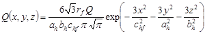 | (7) |
and for the points (x, y, z) belonging to a semi-ellipse coinciding with the rear part of the arc:
| (8) |
where ah , bh , chf , chb are the parameters of the ellipsoidal heat source, Q the applied arc heat, rf, rb proportionality coefficients corresponding to the heat distribution in the front and rear parts of the heat source, where rf + rb = 2.
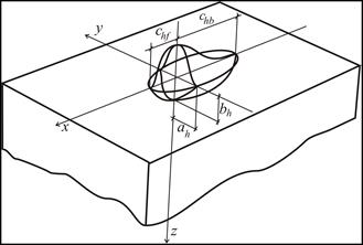
Fig. 4. Double ellipsoidal Goldak’s model of heat source
In the study [7] to describe the temperature field, volume source qv (9) with surface-Gaussian distribution (see Fig. 3) and with the parabolic change in the depth (Fig. 5) fulfilling the condition (10) was introduced instead of the point source.
 | (9) |
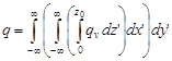 | (10) |
where z0 is the depth of heat source deposition.
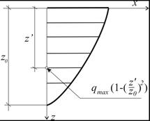
Fig. 5. Parabolic change of the heat source in relation to depth
3. The bimodal model of the welding heat source
Bimodal (double distribution) heat source models are mainly used for a hybrid welding process [8]. With reference to the example of applying the submerged arc, analyzed later in the work, modeling of the temperature field during welding with this technique was examined in works [9-12] among others.
Since the descriptions of the temperature field adopted in these works and based on single-distribution heat source models do not allow for reproduction of often occurring irregular shapes of isotherms in welding practice (including fusion line) during surfacing, in work [13] a double distribution model was proposed. The use of this model has its justification in the method of heat transfer into a surfaced object. The model physically assumes one source of heat - an electric arc. Whereas the temperature field is described by summing up the temperature rises (11) caused by the heat transferred to a surfaced object directly with an electric arc and through the melted electrode material. The drops of the melted electrode material are detached and moved to the developing weld under the influence of electromagnetic forces and their own weight. They are mixed with the molten material of the work piece to form welds.
The discussion assumes that the volume of the electrode molten material is equal to the volume of weld reinforcement, and the amount of heat stored in the molten electrode material equals the quantity of heat transferred to the weld overlay. It is further believed that the wire feed speed of the electrode determines the speed of the melt.
| (11) |
where Ta(x,y,z,t) is the temperature field caused by the heat of the direct impact of an electric arc, and Tw(x,y,z,t) - the temperature field caused by the heat of weld (used to melt the electrodes).
With these assumptions, a volume model of a heat source was adopted for mapping electric arc activity (9), (10) and a source of weld heat of (Fig. 6) was determined as:
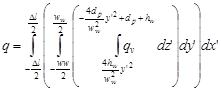 | (12) |
for
| (13) |
The upper bound is a face of the weld determined by the equation:
| (14) |
while the lower bound (in the case of filling e.g. defects), by the equation:
| (15) |
where hw is the height of weld reinforcement, ww the weld width and dp filling depth.
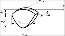
Fig. 6. Geometry of a weld
4. Analysis of the shape and dimensions of the heat affected zone in relation to an adopted heat source model
Calculations of the time varying temperature field during submerged arc welding of a S355J2G3 steel plate with a length of 0.4 m, a width of 0.2 m and a thickness of 0.03 m were performed with the use of the models described in [7] and [13]. These models, based on an analytical solution of a temperature field in the semi-infinite body with the initial-boundary conditions:
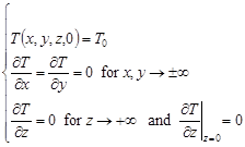 | (16) |
were implemented in programs made in the Borland Delphi environment.
For the adopted welding scheme (Fig. 7), numerical simulations were performed assuming source power used in the experiment: the voltage U = 30 V, current I = 400 A and efficiency factor h = 0.99. Thermo-mechanical properties of the plate material and the electrodes were determined by: a = 8·10–6 m2/s, c = 670 J/kg K, r = 7800 kg/m3 and L = 268 kJ/kg. Just as in the experiment [14], the adopted welding speed was v = 0.007 m/s, electrode diameter d = 3.5 mm, wire feed speed of the electrode ve = 0.031 m/s and the size the weld: the height hw = 2.5 mm and the width ww = 22 mm (Fig. 8). Since the welded surface had no losses (flat), therefore dp = 0. The initial temperature of the electrode (welding head temperature) Te = 100°C was taken as in [15].
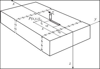
Fig. 7. Single pass weld surfacing scheme
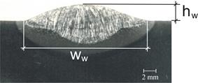
Fig. 8. Metallographic section of the weld
Analysis of the impact of a heat source model on the shape and dimensions of the characteristic heat affected zones was made with the adoption of the following source models:
1) single volumetric,
2) the bimodal: surface model of an electric arc and volumetric model of the weld,
3) the bimodal: volumetric model of an electric arc and volumetric model of the weld.
4.1. Heat affected zone determined by the temperature field caused by a volumetric heat source
The calculations of the temperature field caused by a source (9), (10) with parameters z0 = 0.004 m and t0 = 5 s were performed. Figure 9 shows the calculated characteristic heat affected zones.
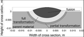
Fig. 9. Calculated heat affected zones
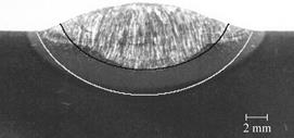
Fig. 10. Comparison of numerical results and image of metallographic section: black and white lines correspond to the calculated fusion line and the calculated temperature limit of the full transformation of austenite A3, respectively
Based on Figure 9 and the experimental verification shown in Figure 10, it can be concluded that the implemented model of a heat source makes it possible achieve a maximum fusion depth. In the middle of the weld, the approximate shapes and the width of the full phase transformation area were mapped. However, mapping of a fusion line and heat affected zones on the edges of the weld was not obtained.
4.2. Heat affected zone determined by the temperature field caused by a bimodal source: a surface model of an electric arc and a volumetric model of the weld
The calculations of the temperature field caused by a bimodal source were carried out: a surface model (6) with t0 = 0.125 s simulating electric arc performance and a volumetric model (12) of the weld. Figure 11 shows the calculated characteristic heat affected zones. On the basis of Figure 11 and the experimental verification shown in Figure 12, it can be concluded that the applied model of a heat source did not allow for mapping of both the shapes and the dimensions of the heat-affected zones.
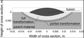
Fig. 11. Calculated heat affected zones
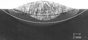
Fig. 12. Comparison of numerical results and image of metallographic section: black and white lines correspond to the calculated fusion line and the calculated temperature limit of the full transformation of austenite A3, respectively
4.3. The heat affected zone determined by the temperature field caused by a bimodal source: a volumetric model of an electric arc and a volumetric model of the weld
Simulations of temperature field were performed with a bimodal source: a volu- metric model (9), (10) with parameters z0 = 0.008 m and t0 = 0.13 s (reproducing arc electric performance) and a volumetric model (12) of the weld. Calculated characteristic heat affected zones (Fig. 13) and their experimental verification reveals a relatively good mapping of both the fusion zone (the fusion line), as well as phase transformation zone. Slight discrepancies occur at the edges of the weld.
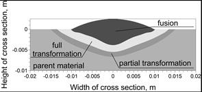
Fig. 13. Calculated heat affected zones
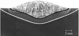
Fig. 14. Comparison of numerical results and image of metallographic section: black and white lines correspond to the calculated fusion line and the calculated temperature limit of the full transformation of austenite A3, respectively
5. Conclusions
Numerical simulations have shown that:
– The model of a single volumetric heat source allows one to achieve a maximum fusion depth. In the middle of the weld, the model makes it possible to determine the approximate shapes and the width of the full phase transformation area. Mapping of a fusion line and heat affected zones on the edges of the weld was not obtained.
– The bimodal heat source composed of a surface model of an electric arc and a volumetric model of the weld source did not allow for mapping of both the shapes and the dimensions of the heat-affected zones.
– The bimodal heat source composed of a volumetric model of an electric arc and volumetric model of the weld allows for a relatively good mapping of both the fusion zone (the fusion line) and phase transformation zone. Slight discrepancies occur at the edges of the weld.
The inclusion of heat of electrode molten material in temperature field modeling enables more accurate mapping of the fusion line shape, and (sufficiently) of heat affected zones. The proposed calculation model is confirmed by the author’s own results of experimental studies and those described in the literature by other authors.
References
[1] Rosenthal D., Mathematical theory of heat distribution during welding and cutting, Welding J. 1941, 20, 220s-234s.
[2] Rykalin N., Fundamentals of Heat Flow in Welding, AN SSSR, Moskva 1947.
[3] Carslaw H.S., Jaeger J.C., Conduction of Heat in Solids, Clarendon Press, London 1996.
[4] Winczek J., Modelling of Weld Surfacing Process with the Use of Volumetric Heat Sources, Monograph, Czestochowa University of Technology Publisher, Czestochowa 2013.
[5] Eagar T.W., Tsai N.S., Temperature fields produced by traveling distributed heat sources, Welding J. 1983, 62, 346s-355s.
[6] Goldak J., Chakravarti A., Bibby M., A new finite element model for welding heat sources, Metal. Trans. 1984, 15B, 299-305.
[7] Winczek J., Analytical solution to transient temperature field in a half-infinite body caused by moving volumetric heat source, Int. J. Heat Mass Transf. 2010, 53, 5774-5781.
[8] Piekarska W., Kubiak M., Three-dimensional model for numerical analysis of thermal phenomena in laser-arc hybrid welding process, Int. J. Heat Mass Transf. 2011, 54, 4966-4974.
[9] Parkitny R., Pawlak A., Piekarska W., Thermal model of submerged arc welding process, Mat. Sci. Tech. 1992, 8, 841-843.
[10] Gunaraj V., Murugan N., Prediction of heat-affected zone characteristics in submerged arc welding of structural steel pipes, Welding J. 2002, 81, 94s-98s.
[11] Pathak A.K., Datta G.L., Three-dimensional finite element analysis to predict the different zones of microstructure in submerged arc welding, Proc. Inst. Mech. Eng. B 2004, 218, 269-280.
[12] Ghosh A., Barman N., Chattopadhyaya S., Hloch S., A study of thermal behaviour during submerged arc welding, Strojniški vestnik - J. Mech. Eng. 2013, 59, 333-338.
[13] Winczek J., New approach to modeling of temperature field in surfaced steel elements. Int. J. Heat Mass Transf. 2011, 54, 4702-4709.
[14] Winczek J., Gawrońska E., The modeling of heat affected zone (HAZ) in submerged arc welding (SAW) surfacing steel element, Metalurgija 2016, 225-228.
[15] Modenesi P.J., Reis R.I., A model for melting rate phenomena in GMA welding, J. Mater. Proces. Techn. 2007, 189, 199-205.