Modeling of mechanical phenomena in the platinum-chromium coronary stents
Aneta Idziak-Jabłońska
,Karolina Karczewska
,Olga Kuberska
Journal of Applied Mathematics and Computational Mechanics |
 Download Full Text |
 View in HTML format |
 Export citation |
@article{Idziak-Jabłońska_2017,
   doi = {10.17512/jamcm.2017.4.03},
   url = {https://doi.org/10.17512/jamcm.2017.4.03},
   year = 2017,
   publisher = {The Publishing Office of Czestochowa University of Technology},
   volume = {16},
   number = {4},
   pages = {29--36},
   author = {Aneta Idziak-Jabłońska and  Karolina Karczewska and  Olga Kuberska},
   title = {Modeling of mechanical phenomena in the platinum-chromium coronary stents},
   journal = {Journal of Applied Mathematics and Computational Mechanics}
}
TY - JOUR DO - 10.17512/jamcm.2017.4.03 UR - https://doi.org/10.17512/jamcm.2017.4.03 TI - Modeling of mechanical phenomena in the platinum-chromium coronary stents T2 - Journal of Applied Mathematics and Computational Mechanics JA - J Appl Math Comput Mech AU - Idziak-Jabłońska, Aneta AU - Karczewska, Karolina AU - Kuberska, Olga PY - 2017 PB - The Publishing Office of Czestochowa University of Technology SP - 29 EP - 36 IS - 4 VL - 16 SN - 2299-9965 SN - 2353-0588 ER -
Idziak-Jabłońska, A., Karczewska, K., & Kuberska, O. (2017). Modeling of mechanical phenomena in the platinum-chromium coronary stents. Journal of Applied Mathematics and Computational Mechanics, 16(4), 29-36. doi:10.17512/jamcm.2017.4.03
Idziak-Jabłońska, A., Karczewska, K. & Kuberska, O., 2017. Modeling of mechanical phenomena in the platinum-chromium coronary stents. Journal of Applied Mathematics and Computational Mechanics, 16(4), pp.29-36. Available at: https://doi.org/10.17512/jamcm.2017.4.03
[1]A. Idziak-Jabłońska, K. Karczewska and O. Kuberska, "Modeling of mechanical phenomena in the platinum-chromium coronary stents," Journal of Applied Mathematics and Computational Mechanics, vol. 16, no. 4, pp. 29-36, 2017.
Idziak-Jabłońska, Aneta, Karolina Karczewska, and Olga Kuberska. "Modeling of mechanical phenomena in the platinum-chromium coronary stents." Journal of Applied Mathematics and Computational Mechanics 16.4 (2017): 29-36. CrossRef. Web.
1. Idziak-Jabłońska A, Karczewska K, Kuberska O. Modeling of mechanical phenomena in the platinum-chromium coronary stents. Journal of Applied Mathematics and Computational Mechanics. The Publishing Office of Czestochowa University of Technology; 2017;16(4):29-36. Available from: https://doi.org/10.17512/jamcm.2017.4.03
Idziak-Jabłońska, Aneta, Karolina Karczewska, and Olga Kuberska. "Modeling of mechanical phenomena in the platinum-chromium coronary stents." Journal of Applied Mathematics and Computational Mechanics 16, no. 4 (2017): 29-36. doi:10.17512/jamcm.2017.4.03
MODELING OF MECHANICAL PHENOMENA IN THE PLATINUM-CHROMIUM CORONARY STENTS
Aneta Idziak-Jabłońska 1, Karolina Karczewska 2, Olga Kuberska 2
1
Institute of Mechanical Technology, Czestochowa University of Technology
Czestochowa, Poland
2 Student Scientific Society of Biomedical Engineering, Institute of
Mechanical Technology
Czestochowa University of Technology, Czestochowa, Poland
idziak-jablonska@iop.pcz.pl, Karczewska-Karolina@wp.pl, kuberska.olga@gmail.com
Received: 23 August 2017; Accepted: 30 November 2017
Abstract. This study discusses the geometrical model of a coronary stent with known design and strength analysis using the finite element method. The coronary stent model was made of platinum and chromium alloy. Static analysis based on compression of the coronary stent was also performed. The aim of the analysis was to examine the strength of the stent structure. The study analyzed stresses, plastic strains and displacements after applying a constant load to the stent walls. The mechanical phenomena such as percentage degree of shortening (foreshortening), relative narrowing and area of stent covering were also determined.
MSC 2010: 92C10, 74L15, 65
Keywords: mathematics, computational mechanics, platinum-chromium stent, FEM, SolidWorks
1. Introduction
One of the biggest successes in the field of invasive cardiology was to use endovascular implants termed stents. These implants are designed as small metal wirings with a cylindrical design. They are implanted in the location of the narrowed coronary artery in order to expand it and support the arterial walls. Stents have been used in hemodynamic laboratories in percutaneous coronary interventions to treat coronary artery disease [1].
All the materials used for stents do not damage the structure of proteins and do not impact blood morphology. Stents cannot lead to inflammatory reactions after they are implanted in the human body. The most popular materials used for coronary stents include austenitic steel Cr-Ni-Mo (316 L), cobalt alloys, platinum and iridium alloys, nitinol and titanium and its alloys [2, 3].
Compared to stainless steel (surgical steel 316L), platinum-chromium alloy used in this study allows for a reduction in bending resistance and has a better fit. Stents made of platinum-chromium alloys were also designed in order to improve the visibility on X-ray images and increase radial force. The PtCr alloy is characterized by greater density compared to surgical steel 316L. Therefore, it is more visible in X-ray images despite smaller components in the stent. Studies have also shown that stents made of platinum-chromium alloys are faster covered by the neointima. Its flexibility allows for easier movement through the arteries without causing damage. The addition of platinum with a high melting point also offers improved corrosion resistance, which optimizes long-term stability of the stent in the human body [4].
The effectiveness of using coronary stents is also ensured by the physicochemical properties of the surfaces used on the endovascular implants. Therefore, the major focus is on the development of the technologies of application of coatings on the metal stent that reduce the process of blood coagulation and ensure internal biotolerance in the human body. Endovascular implants can be covered by polymeric coatings, inorganic coatings and surfaces that release drugs. The polymeric coatings include the non-biodegradable materials e.g. polyurethane (PU) and phosphorylcholine (PC) and natural origin: cellulose and polylactic acid,(PLA). New types of stents that release drugs (Drug Eluting Stents) have also been used in the intervention cardiology [5].
The parameters that characterize endovascular implants include:
– elastic internal return of stents due to the elastic deformation of the implant material. This parameter is measured as a condition concerning the relative reduction in the stent diameter after removing the balloon [6]:
|
|
|
where:
![]() - implant diameter
before deflation of the balloon from the catheter,
- implant diameter
before deflation of the balloon from the catheter, ![]() - implant diameter
after balloon deflation,
- implant diameter
after balloon deflation,
– intrinsic elastic recoil (IER) caused by the reduction in the diameter of the expanded stent after removing the pressure [7]:
| (2) |
where:
![]() –
diameter of the expanded stent,
–
diameter of the expanded stent, ![]() - implant diameter
after deflation of the balloon from the catheter,
- implant diameter
after deflation of the balloon from the catheter,
– measurement of the relative reduction of the implant length after removing the balloon from the catheter; longitudinal recoil is necessary for presentation for the foreshortening after deflation of the balloon from the catheter [6]:
|
|
|
– recoil is defined through determination of the percentage difference in the implant diameter between the biggest external diameter after expansion of the balloon to the final external diameter after removing the balloon. Mean percentage recoil can be determined using the equation [8]:
|
|

– implant compression strength as a resistance to external compression forces. This strength is defined as a pressure needed to reduce the implant diameter by 10% immediately after implantation and intrinsic elastic recoil. Calculation of the external compressive pressure consists in determination of the pressure that is used on the whole surface of the implant for its deformation [6].
Additional conditions that characterize endovascular implants are:
– stent flexibility, which is used as a point of reference for the determination of the opportunities for placing the stent in a specific arterial region. Stent flexibility is defined as inverse bending stiffness and expressed by the following formula [7]:
|
|
|
where: EI - bending stiffness, p - pressure, L - length, w - deflection, δ - stent width,
– stent coverage area is defined as percentage evaluation between the external surface of metal in contact with the surface of the wall of the cylindrical vessel, which represents the fraction of the stented artery surface segment actually covered by metal. In order to prevent the occurrence of restenosis, the area between the stent and vessel wall should be minimized [6]:
|
|
|
– dogboning according to the standard [8-10] is defined as a balloon diameter exceeding the stent's ends, greater from the external stent diameter at the highest inflation pressure. The examination is aimed at determination of the difference in diameters between balloon during the biggest recommended inflation pressure and the moment when the stent is expanded. This parameter provides information about potential damages to the vessel outside the stent.
In other studies, dogboning is defined by the following formula:
|
|
|
where:![]() - distal stent diameter,
- distal stent diameter, ![]() - central stent diameter.
- central stent diameter.
– longitudinal shortening after expansion of the stent is presented as a percentage degree of shortening. The dimensions of the stents can be modified (shortened) during stent implantation, which has an effect on the final stent length. Knowledge of the shortening parameters is useful in choosing the adequate stent length and using it in the right position in the human body [8,10].
|
|
|
where:
![]() - initial stent
length,
- initial stent
length, ![]() - stent length at the highest loading.
- stent length at the highest loading.
– relative narrowing (normal strain) - narrowing of the stent diameter caused by compression related to its initial diameter. It is defined as:
|
|
|
where:
![]() - initial stent
diameter before compression,
- initial stent
diameter before compression, ![]() - the smallest stent
diameter after compression;
- the smallest stent
diameter after compression;
– analysis of stress and strain should present substantial differences between the observed and modelled deformations. Deformations should be presented in percentage terms, whereas stresses should be expressed in MPa [8, 10]. If the FEM method is used, the types of used elements should be recognized [11].
2. Material and methods
2.1. Stent model
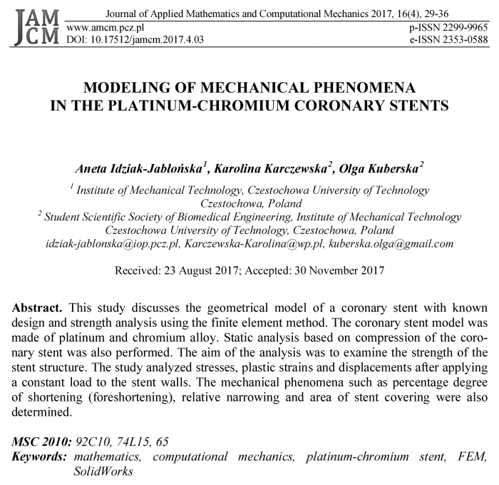
The geometrical model of the stent was developed using the SolidWorks 2014 software (Fig. 1). With regard to its shape, the stent is numbered among net stents.
The length of the developed model is 13.03 mm, internal diameter is 2 mm, both thickness and width of walls is 0.06 mm. The stent was composed of 8 segments. Due to its design, stent geometry is based on the intersecting walls with a rectangular profile, forming free diamond-shaped spaces.
Static analysis was performed by means of the SolidWorks 2014 software using the finite element method (FEM). A solid grid composed of 91052 nodes and 35711 elements was created for the stent model.
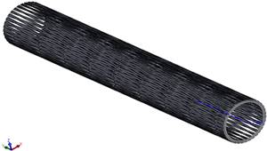
Fig. 1. Stent model with applied forces and stent fixation
2.2. Material properties of the model
Due to high biocompatibility and strength, mechanical calculations were based on mechanical properties of the material contained in the SolidWorks database for platinum-chromium alloy. Stents made of platinum-chromium alloy have greater density and are more quickly covered by the neointima compared to the conventional stents made of steel 316 L. Table 1 presents material data adopted in the study.
Table 1
Material properties of the platinum-chromium alloy
|
Material properties |
Value |
|
Young’s modulus E [MPa] |
203 000 |
|
Poisson’s ratio v |
0.285 |
|
Density ρ [kg/m3] |
7850 |
|
Tensile strength Rm [MPa] |
834 |
|
Yield point Rp0,2 [MPa] |
480 |
2.3. Fixation conditions and stent compression
In order to perform a numerical analysis, apart from the adopted material properties, it is also important to define boundary conditions. For this purposes, the stent model was fixed at its two ends.
It is necessary to reduce the initial diameter of the implant in order to ensure proper implantation of the stent in the position of the artery narrowing. Furthermore, an insignificant diameter reduction protects from the possibility of removing from the catheter surface. The aim of the study is to evaluate the stent compression strength. It was adopted that the surgeon acts with a specific force on the external stent surface. At the time of surgery the doctor uses force 10¸15 N. Therefore, the stent model was loaded on both ends with the force of 10 N on four external walls. Figure 2 presents stent model with applied forces and stent fixation.
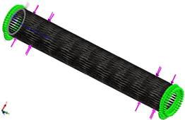
Fig. 2. Stent model with applied forces and stent fixation
For this stent model, stresses, strain and displacement area were determined.
3. Results of numerical analysis
1. Distribution of reduced stresses - Figure 3
For the coronary stent model made of PtCr alloy with applied forces, distribution of stresses was varied. The maximal value of reduced stresses was observed at the end of the external wall in the locations where the was stent fixation. The maximal value of stresses was 29.86 MPa, whereas minimal stresses were around 1.533 MPa.
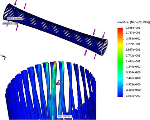
Fig. 3. Map of the reduced stress for stent made of PtCr alloy
2. Distribution of plastic strains - Figure 4a
The plastic strains generated during the strength test are permanent displacements which do not yield even after removing the load they were caused by. The biggest plastic strain was observed on the external stent walls, next to its fixation and accounted for 9.7%.
3. Distribution of displacements - Figure 4b
Apart from distribution of stresses, strain and displacements were also observed for the stent made of platinum-chromium alloy. The highest value of displacement was 0.303 mm, wheras the smallest was 0 mm. The biggest displacement was located on the external stent walls, next to its fixation and force application point, whereas tha smallest displacements are observed on the internal ends of the model.
a)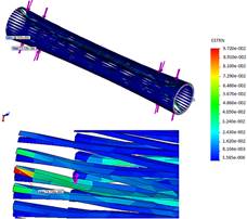 b)
b)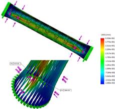
Fig. 4. Distribution of plastic strain (a) and displacement (b) for stent
4. Conclusions
Statistical analysis performed using the finite element method allowed for the evaluation of stent strength. Furthermore, based on its value, the percentage foreshortening and relative narrowing caused by plastic strain was determined.
· The examinations revealed that the yield limit wasn’t exceeded in the analyzed case, which could lead to irreversible plastic deformation of the geometry of the stent.
· The force of 10 N does not cause high stresses and does not even exceed the yield point. Activation of too much force will lead to permanent deformation, making it impossible to expand the stent. Excessive force would lead to permanent deformation, preventing the stent from expanding.
· The highest plastic strains are noticed on the external model walls in the locations of slight bending of the stent walls. They can lead to irritation of the internal walls of arteries and inflammatory reactions or complications following the surgery.
· The results obtained from the biomechanical analysis of coronary stents carried out in the present study based on finite element method represent information that can be useful for optimization of the geometry, choice of mechanical properties and material properties of the stent.
· The static analysis performed using the finite element method allowed for evaluation of stent strength. The stent structures which are the most exposed to risk of damage during model compression were demonstrated. The study showed that an important aspect of stent design is the adequate choice of material and model geometry.
· The analysis carried out in the study allowed for identification of the parameters critical to evaluation of clinical usefulness of a specific stent shape.
References
[1] Paszenda Z., Stenty w kardiologii interwencyjnej. Wybrane zagadnienia, Wydawnictwo Politechniki Śląskiej, Gliwice 2013 (in Polish).
[2] Paszenda Z., Kształtowanie własności fizykochemicznych stentów wieńcowych ze stali Cr-Ni-Mo do zastosowań w kardiologii zabiegowej, Wyd. Politechniki Śląskiej, Gliwice 2005 (in Polish).
[3] Idziak-Jabłońska A., Numerical analysis of mechanical phenomena in coronary stent made of titanium alloy Ti-13Nb-13Zr, Key Engineering Materials 2016, 687, 191-198.
[4] O’Brien B.J., Stinson J.S., Larsen S.R., Eppihimer M.J., Carroll W.M., A platinum-chromium steel for cardiovascular stents, Biomaterials 2010, May 31(14), 3755-3760.
[5] Paszenda Z., Stenty w chirurgii małoinwazyjnej, Wydawnictwo Politechniki Śląskiej, Gliwice 2006 (in Polish).
[6] Annicchiarico W., Dulikravich G.S., Multiobjective nonlinear shape optimization of stent based on evolution principles. Inverse Problems, Design and Optimization Symposium, Miami, Florida, U.S.A., April 16-18, 2007.
[7] Li N., Zhanga H., Oyyang H., Shape optimization of coronary artery stent based on a parametric model. Finite Elements in Analysis and Design 2009, 45, 468-475.
[8] Norma PN-EN ISO 25539-2 Implanty sercowo-naczyniowe - Wyroby wewnątrznaczyniowe - Część 2: Stenty naczyniowe.
[9] Idziak-Jabłońska A., Lacki P., Major R., Effect of material and geometry on Dogboning in coronary stent, Inżynieria Materiałowa 2013, 4, lipiec-sierpień, 269-272.
[10] Idziak-Jabłońska A., Modelowanie zjawisk mechanicznych w stentach wieńcowych na podstawie analizy numerycznej, Mechanik 2015, 7, 303-310 (in Polish).
[11] Zienkiewicz O.C., Taylor R.L., The Finite Element Method, vol. 1-3, Butterworth-Heinemann, Oxford 2000.